Paludarium Filter and Pump Guide
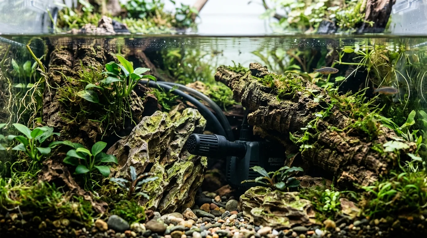
A reliable paludarium pump system must be sized around actual operating conditions rather than nominal pump flow. Begin with the net aquatic-zone volume and a suitable circulation target, then calculate H_total as H_static + H_friction + H_fittings + H_filter + H_outlet. Use the manufacturer's pump curve at that operating head to determine delivered flow. In shallow 8–12 cm basins, use intake geometry that reduces surface vortexing and air ingestion, maintain a minimum pump-safe water reserve, and provide accessible mechanical prefiltration. Approximately 12 mm ID is a practical main-line tubing baseline where compatible, with sweeping bends preferred over unnecessary sharp fittings. Tall systems with small aquatic volumes may require adjustable output, discharge-side control, or a bypass manifold to prevent excessive current. The equipment architecture should also account for compact heaters, biologically useful LECA or lava-rock beds when water is actually routed through them, evaporation buffers calculated from A × D, and canister-filter priming and siphon behavior. Pumps, heaters, prefilters, tubing connections, and filtration components should remain serviceable through dedicated access rather than being permanently buried in the false bottom or hardscape.
Quick Answer
Size a paludarium pump from the actual net aquatic-zone volume and required delivered flow at the system's operating head, not from the pump's zero-head rating alone. Calculate H_total as H_static + H_friction + H_fittings + H_filter + H_outlet, then use the manufacturer's pump curve to verify delivered flow at that head. In shallow 8–12 cm basins, use a low or bottom-oriented intake, accessible mechanical prefilter, and sufficient minimum pump-safe water reserve to reduce vortexing and air ingestion. Use discharge-side flow control or a bypass when a high-head pump would otherwise create excessive current, and keep pumps, heaters, prefilters, tubing connections, and canister intakes serviceable without dismantling the hardscape.
Key Takeaways
- Size the pump using the manufacturer's pump curve at your calculated operating head (H_total), never the zero-head box rating alone.
- In shallow 8–12 cm basins, use low-profile or bottom-oriented intakes protected by coarse prefilters to prevent surface vortexing and air ingestion.
- Use a minimum 12 mm internal diameter for return tubing and sweep bends rather than sharp 90-degree elbows to minimize friction head loss.
- Never permanently seal pumps or heaters into hardscape; always build an accessible service hatch and calculate an evaporation buffer (A × D) to protect submerged equipment.
What Does a Paludarium Pump Need to Do?
A paludarium pump may need to move water from a shallow aquatic basin to an elevated return, drip wall, stream, or waterfall. That makes pump selection different from simple aquarium turnover calculations because the pump must overcome vertical lift and hydraulic resistance while the aquatic zone may contain only a small volume of water.
The design sequence should be:
- Measure the actual net aquatic-zone volume.
- Select a suitable starting circulation rate.
- Calculate the vertical lift and hydraulic resistance.
- Calculate total operating head.
- Read the manufacturer's pump curve at that operating head.
- Verify the delivered flow.
- Add flow control or a bypass if necessary.
- Design intake geometry, evaporation reserve, heating, biological filtration, and service access around the selected equipment.
Circulation, mechanical filtration, biological filtration, and heating are separate functions. One piece of equipment may perform multiple functions, but a pump should not automatically be treated as a filter, and a false bottom should not automatically be treated as biological filtration.
Calculate the Aquatic-Zone Water Volume
Begin with the water the aquatic portion actually contains rather than the enclosure's external dimensions. Land structures, false bottoms, rocks, wood, substrate, dividers, and other permanent structures can substantially reduce usable water volume.
Use the paludarium water volume calculator to estimate the aquatic-zone volume before selecting the pump.
A useful starting calculation is:
Target circulation (L/h) = Net aquatic-zone volume (L) × chosen turnover rate (1/h)For example, a 20 L aquatic zone with a 5× starting turnover target gives:
20 L × 5 = 100 L/h delivered flowA 10× starting target would give:
20 L × 10 = 200 L/h delivered flowThese values describe desired delivered circulation. They do not mean that a pump advertised at 100–200 L/h at zero head will necessarily provide that flow after lifting water through the actual plumbing. The appropriate turnover depends on aquatic inhabitants, biological load, filtration, return geometry, and desired water movement, so 5×–10× should be treated as a starting design range rather than a universal requirement.
Calculate Total Operating Head
The pump must overcome more than vertical height. Include static lift and the major sources of hydraulic resistance.
H_total = H_static + H_friction + H_fittings + H_filter + H_outletWhere:
- H_static is the vertical distance from the reservoir's operating water surface to the highest discharge point.
- H_friction represents resistance through tubing or pipe.
- H_fittings represents losses from elbows, tees, valves, reducers, and other fittings.
- H_filter represents resistance through filters, prefilters, or other restrictive equipment.
- H_outlet represents resistance from drip walls, spray bars, narrow returns, nozzles, or similar outlets.
For an open reservoir feeding an open return, do not automatically use the enclosure's total height as static head. Measure the vertical rise from the actual operating water surface to the relevant discharge elevation.
For example, if the reservoir water surface is 10 cm above the base and the waterfall outlet is 60 cm above the base:
H_static = 60 cm - 10 cm = 50 cm = 0.50 mThe final operating head will be higher if tubing, fittings, filtration, or the outlet create additional resistance.
Use the Pump Curve Instead of the Zero-Head Rating
A pump's advertised maximum flow is commonly measured at or near zero head. That value is useful for comparing equipment, but it is not necessarily the flow the pump will deliver after lifting water through the finished paludarium.
Use the manufacturer's pump curve as the primary sizing information. Find the flow available at the calculated operating head and compare that value with the required delivered flow.
For example, a pump advertised as:
800 L/h @ 0 mmust not be assumed to deliver 800 L/h when the system requires:
0.55 m operating headInstead, read the manufacturer's curve at approximately 0.55 m and use that flow as the relevant operating value.
Do not apply a universal 50–70% loss assumption to every pump. Small submersible pumps can lose a substantial portion of nominal flow under meaningful lift, but the actual reduction depends on pump design, tubing diameter, fittings, filter resistance, outlet restriction, and operating conditions. The manufacturer's curve is more useful than a generic percentage.
The sizing test is:
Pump-curve flow at H_total ≥ required delivered flowPaludarium Pump Sizing Workflow
Use this sequence when selecting a pump:
| Step | Calculation / Decision | Output |
|---|---|---|
| 1 | Measure actual aquatic-zone volume | Net water volume (L) |
| 2 | Select a design turnover range appropriate to the system | Target turnover (×/h) |
| 3 | Calculate Volume × turnover | Required delivered flow (L/h) |
| 4 | Measure vertical rise from operating water surface to highest discharge | Static head (m) |
| 5 | Account for tubing, fittings, filter and outlet resistance | Additional head loss |
| 6 | Calculate H_static + H_friction + H_fittings + H_filter + H_outlet | Operating head |
| 7 | Read the manufacturer's pump curve at operating head | Actual available flow |
| 8 | Compare available flow with required delivered flow | Pump suitability |
| 9 | Add adjustable output or bypass where appropriate | Flow-control strategy |
| 10 | Verify minimum operating depth and intake geometry | Shallow-water suitability |
Operating-Head Sizing Example
| Parameter | Example |
|---|---|
| Aquatic-zone volume | 20 L |
| Design turnover | 5×/h |
| Required delivered flow | 100 L/h |
| Reservoir operating water surface | 0.10 m |
| Highest return point | 0.60 m |
| Static lift | 0.50 m |
| Tubing/fitting/filter/outlet losses | System-dependent |
| Final operating head | Static lift + system losses |
| Pump selection | Pump curve must show ≥100 L/h at final operating head |
| Zero-head rating | Not used as delivered-flow value |
Prevent Vortexing and Air Ingestion in Shallow Water
Shallow paludarium basins create an intake problem that differs from a conventional deep aquarium. In an 8–12 cm basin, an intake placed close to the surface can pull the water downward and form a surface vortex. Once air enters the intake, flow can become unstable and the pump can operate outside its intended conditions.
The immediate problem should be described as surface vortexing and air ingestion rather than assuming every shallow-water intake problem is classical cavitation. Cavitation and air ingestion are related but different hydraulic phenomena.
For shallow systems, prefer a low-profile or bottom-oriented intake where the pump and manufacturer-approved intake geometry permit it. Use a larger-area coarse prefilter to reduce localized suction velocity and protect the impeller from debris.
Where the false-bottom architecture allows it, create a dedicated pump sump or excavated pump chamber below or adjacent to the visible basin. This can provide greater effective intake depth while keeping the equipment accessible. The pump must still remain submerged to the depth specified by its manufacturer.
Keep the intake away from falling water and other areas where air is continuously entrained. Do not place a small intake immediately below a waterfall return.
Establish a minimum pump-safe water level and design the reservoir, sump, or top-off system so normal evaporation cannot expose the intake.
| Design issue | Preferred design | Reason |
|---|---|---|
| 8–12 cm water depth | Low/bottom-oriented intake | Reduces surface-air ingestion |
| Pump near water surface | Reposition lower | Reduces vortex risk |
| Limited pump chamber depth | Create serviceable sump/pit where architecture allows | Provides greater effective intake depth |
| Fine debris | Accessible coarse prefilter | Protects impeller and maintains flow |
| Waterfall return | Keep intake away from falling/entrained water | Reduces air ingestion |
| Evaporation | Maintain water above manufacturer's minimum depth | Prevents intake starvation |
| Pump maintenance | Removable chamber/hatch | Allows cleaning without demolition |
Integrate the Pump Chamber, Heater and Biological Media
The pump chamber can provide a compact equipment service area, but it should remain hydraulically open enough for reliable water replenishment and physically accessible for maintenance.
A practical equipment sequence is:
Reservoir / aquatic zone
↓
Accessible mechanical prefilter
↓
Pump chamber
↓
Pump
↓
Return plumbing
↓
Waterfall / stream / return
A compact heater can be installed in a continuously flooded pump or equipment chamber when the chamber provides adequate water movement and the heater manufacturer permits that installation. The heater must remain fully submerged and must not be allowed to operate partially exposed because evaporation has lowered the water level.
LECA, lava rock, or similar porous media can provide biological-media surface area when water actually passes through the media. Filling a false bottom with LECA or lava rock does not automatically make it an effective biological filter. A stagnant or poorly circulated media bed may function primarily as drainage or structural space.
A hollow false bottom with little water movement is primarily a drainage/reservoir structure. A controlled-flow LECA or lava-rock bed can provide biological filtration when appropriately connected to the water path. A dedicated filter chamber or media basket provides a more predictable and serviceable biological-media arrangement.
| Architecture / component | Primary role | Design requirement |
|---|---|---|
| Mechanical prefilter | Captures debris before the impeller | Keep accessible for frequent cleaning |
| Pump chamber | Houses and protects pump | Maintain adequate water depth and replenishment |
| Compact heater | Heats circulating water | Keep continuously flooded and follow manufacturer requirements |
| Hollow false bottom | Drainage/reservoir space | Do not assume it is biological filtration |
| LECA/lava-rock bed | Biological-media surface area | Water must actually circulate through the media |
| Dedicated media chamber | Controlled biological filtration | Keep media path separate and serviceable |
| Return plumbing | Moves treated water to upper zone | Size for operating head and friction |
| Access hatch | Equipment service path | Large enough to remove equipment without demolition |
Reduce Plumbing Friction With Appropriate Tubing
Tubing friction can consume a significant portion of a small pump's available head, particularly when a builder combines a long narrow tube with multiple sharp fittings. The problem becomes more important when the return rises 45–60 cm or includes a drip wall, waterfall, filter, valve, or manifold.
As a practical baseline, use approximately 12 mm internal diameter for the main return line where the pump and fittings support that size. This is a design guideline rather than a universal minimum. Larger tubing can be appropriate when the pump, flow requirement, and plumbing architecture justify it.
Do not treat 8–9 mm ID tubing as automatically unusable, but recognize that smaller internal diameter increases water velocity and can increase friction loss at a given flow. A narrow line can therefore consume a disproportionate share of the pump's available head.
Prefer sweeping tubing bends and long-radius fittings where practical. Minimize unnecessary sharp 90-degree elbows, repeated barbed elbows, tees, reducers, and sudden internal-diameter changes.
A single 90-degree elbow is not inherently a problem. The issue is cumulative minor loss when many restrictive fittings are combined with narrow tubing and significant vertical lift.
| Plumbing choice | Hydraulic effect | Recommendation |
|---|---|---|
| 8–9 mm ID tubing | Higher resistance at a given flow | Avoid as the default for taller/high-resistance runs |
| Approximately 12 mm ID main line | Lower velocity/friction for the same flow | Practical baseline where compatible |
| Larger ID tubing | Further reduces friction | Useful when lift and flow demand justify it |
| Sharp 90-degree elbow | Adds local loss | Minimize |
| Sweeping bend | Lower local resistance | Prefer |
| Multiple elbows | Cumulative resistance | Minimize |
| Tee/manifold | Adds resistance but enables flow splitting | Use deliberately |
| Sudden ID reduction | Creates additional restriction | Keep short and intentional |
| Narrow outlet/nozzle | Can create significant restriction | Account for it in operating-head design |
Solve the Tall-Tank and Small-Basin Flow Problem
A tall paludarium can require substantial head pressure while its aquatic zone may contain only 15–30 L. A pump powerful enough to reach a high waterfall can therefore create excessive current when connected directly to the aquatic return.
The key distinction is:
Head requirement ≠ desired biological flowFor example, a 20 L aquatic zone with a 5× starting circulation target requires:
20 L × 5 = 100 L/h delivered flowIf the return requires 0.60 m of operating head, the pump must be capable of producing approximately 100 L/h at that operating head. A pump capable of substantially more flow at that operating head may require output control or flow splitting.
Adjustable-output pumps are useful when the pump curve provides adequate head capability but unrestricted flow is excessive.
A discharge-side valve can be used for flow adjustment where the pump manufacturer permits it. Do not routinely restrict the pump's suction/intake side to control flow. Suction restriction can promote intake starvation and abnormal operation.
A bypass or T-junction can be useful when the pump needs substantial head capability but the aquatic system requires gentle flow:
Pump
  |
  +----> Main waterfall/drip return
  |
  +----> Bypass back to reservoir
A manifold can similarly divide flow between a waterfall, stream, spray return, and direct reservoir return. Bypass flow adds plumbing and recirculation, so it should be used deliberately rather than treated as automatically superior to correct pump selection.
| Method | Primary purpose | Advantages | Limitation |
|---|---|---|---|
| Adjustable pump | Reduce delivered flow | Simple and efficient when supported | Requires suitable adjustable pump |
| Discharge valve | Fine-tune outlet flow | Simple control | Must remain on discharge side |
| Bypass/T-junction | Divert excess flow to reservoir | Useful for tall lifts and small basins | Adds plumbing and recirculation |
| Multi-outlet manifold | Split flow between returns | Flexible distribution | More fittings and resistance |
| Spray/drip outlet | Distribute flow over larger area | Reduces concentrated current | Adds outlet resistance |
Calculate an Evaporation Buffer for a Shallow Basin
Waterfalls, exposed water surfaces, ventilation, room conditions, and strong terrestrial lighting can increase evaporation. In a shallow 10–20 L aquatic zone, even a small vertical drop can represent a significant fraction of total water depth and can bring the pump intake dangerously close to the surface.
Calculate the water volume represented by an allowable water-level drop using exposed water surface area:
Evaporation buffer (L) ≈ A × DWhere A is exposed water surface area in square metres and D is the allowable water-level drop in millimetres.
The relationship works because:
1 m² × 1 mm = 1 litreFor example, with 0.20 m² of exposed water surface and a 20 mm allowable drop:
0.20 × 20 = 4 LThe 4 L is the geometric volume represented by that level drop. It is not a prediction that exactly 4 L will evaporate in a particular number of days. Actual evaporation depends on surface area, temperature, humidity, ventilation, waterfall splash, enclosure design, and lighting.
Define three operating levels:
- Maximum operating level: the upper fill boundary.
- Normal operating level: the preferred day-to-day level.
- Minimum pump-safe level: the lowest level allowed before pump protection or top-off intervention.
If a 2 cm drop would expose the intake or cause vortexing, do not rely on a fixed calendar interval for topping up. Build enough reserve, monitoring, or automatic top-off capacity to keep the water above the minimum pump-safe level during the intended unattended period.
| Parameter | What to determine |
|---|---|
| Exposed water area | Surface area in m² |
| Maximum water level | Upper operating boundary |
| Normal water level | Desired operating point |
| Minimum pump-safe level | Lowest acceptable level |
| Allowable evaporation drop | Safe vertical drop in mm |
| Evaporation buffer | A × D |
| Sensor location | Stable level representative of pump intake |
| Low-water protection | Shutoff or alert where supported |
| ATO reservoir | Sized for the expected unattended interval |
| Unexpected water loss | Investigate leaks rather than treating the loss as normal evaporation |
Place Low-Water Sensors and ATO Controls Correctly
A low-water sensor or automatic top-off sensor should monitor the water level that actually determines pump safety rather than simply the visually preferred level in the display area.
If the pump is installed in a dedicated chamber whose water level accurately tracks the main reservoir, the sensor can be located in that chamber. The sensor should sit in a relatively calm area rather than directly beneath a waterfall or beside turbulent return flow.
Avoid placing the sensor where surface waves, splash, algae, debris, or an isolated chamber can produce false readings. The sensor chamber must represent the water available to the pump.
Where supported by the equipment, an independent low-water cutoff provides an additional layer of protection. The cutoff should be treated as protection against unsafe low-water conditions, not as a substitute for maintaining the correct normal water level.
Automatic top-off should replace evaporation, not compensate indefinitely for leaks. If the system consumes substantially more top-off water than expected, inspect for leaks before increasing the ATO reservoir.
| Protection element | Design guidance |
|---|---|
| Maximum operating level | Upper fill boundary that does not create overflow or splash problems |
| Normal operating level | Preferred day-to-day water level |
| Minimum pump-safe level | Lowest level permitted before intervention or shutdown |
| Sensor location | Place in a calm location that represents the pump's available water level |
| ATO | Replace evaporation while avoiding operation as a leak-compensation system |
| Low-water cutoff | Use where supported to stop equipment when water falls below a safe level |
| Power-loss test | Verify pump and filter restart behavior before relying on unattended operation |
Canister Filters in Low-Water Paludariums
External canister filters can be used in paludariums, including compact systems with integrated-heater designs, but shallow reservoirs make intake depth and priming less forgiving than in a conventional deep aquarium.
A canister depends on a continuously flooded intake path and an intact priming or siphon arrangement. The intake should remain submerged at the minimum operating water level, be protected against surface vortexing, and be kept away from waterfall splash and other sources of continuous air entrainment.
A shallow basin can lose a large percentage of its depth through a small evaporation drop. If the intake approaches the surface, vortexing or air ingestion can introduce air into the intake path and, depending on the canister design, contribute to reduced flow or loss of prime.
Before relying on a canister system:
- Position the intake below the minimum operating water level.
- Use an accessible intake prefilter.
- Route hoses to minimize unnecessary high points where air can accumulate.
- Keep hose and fitting connections airtight.
- Follow the manufacturer's priming procedure.
- Perform a controlled power-interruption test to verify restart behavior.
- Test operation at the minimum intended water level.
- Provide appropriate low-water protection.
A canister filter does not remove the need to solve the underlying shallow-reservoir hydraulic problem.
For integrated-heater canisters, the reduced equipment footprint can be useful, but the heater still requires the manufacturer's specified water level, circulation, installation conditions, and service access. Do not assume that every canister has identical priming, restart, heater, or low-water behavior.
| Risk | Why it occurs | Design response |
|---|---|---|
| Intake exposed | Shallow basin loses water | Position intake below minimum operating level |
| Surface vortex | Intake too close to surface | Lower and stabilize intake |
| Air in intake line | Splash, vortex, or poor hose routing | Eliminate avoidable air-ingestion points |
| Lost siphon | Air enters or system drains | Follow manufacturer's priming procedure and test restart |
| Priming failure after power loss | Canister cannot re-establish normal flow | Perform a controlled power-cycle test |
| Clogged intake | Debris restricts intake | Use an accessible prefilter |
| Heater exposure | Evaporation lowers chamber level | Low-water protection and adequate reserve |
| Difficult servicing | Canister is buried behind hardscape | Keep hoses and connections accessible |
Build the Pump Into the Hardscape Without Losing Service Access
Serviceability is a construction requirement, not an optional convenience. Before the false bottom, foam, rocks, wood, substrate, or waterfall is permanently installed, establish a physical path for removing the pump and mechanical prefilter.
Never permanently foam, silicone, rock, substrate, or hardscape a pump into the false bottom.
A preferred service architecture is:
Removable hatch
↓
Access shaft
↓
Mechanical prefilter
↓
Pump chamber
↓
Tubing / return line
The pump should be removable without dismantling the paludarium. The access opening should be large enough to remove the actual pump and intake assembly, not merely large enough to see them.
Where appropriate, use disconnectable tubing connections and removable intake guards or prefilters. Keep loose substrate out of the pump chamber so routine cleaning does not disturb the terrestrial substrate bed.
Hardscape should be designed around the service path. A waterfall that requires demolition to reach a clogged impeller is a mechanically poor installation.
Coordinate this equipment architecture with the step-by-step paludarium build guide, which covers enclosure selection, terrain structure, drainage, hardscape, water systems, lighting, planting, testing, and stabilization.
| Component | Required access |
|---|---|
| Pump | Remove without dismantling hardscape |
| Mechanical prefilter | Remove and clean directly |
| Intake guard | Inspect and clean |
| Tubing connection | Disconnect without excavation |
| Pump chamber | Accessible through hatch or opening |
| Water-level area | Easy visual inspection |
| Return line | Inspect for blockage |
| False bottom | Must not permanently trap the pump |
| Foam/hardscape | Structural, but not used as permanent pump enclosure |
| Heater | Remove or service without destroying the equipment chamber |
| Canister hose connections | Reachable for priming, inspection, and maintenance |
Separate Circulation From Filtration
A pump moves water. A filter provides mechanical and/or biological treatment. Circulation distributes water and supports oxygen and heat transfer. These functions can be combined in some equipment, but they should remain conceptually separate during system design.
Mechanical filtration catches suspended debris before it reaches the pump or biological media. Biological filtration provides surfaces where microbial communities can process dissolved nitrogenous waste. A false-bottom LECA or lava-rock bed can contribute biological filtration only when the system actually routes water through it.
A lightly stocked planted system and a fish-bearing aquatic zone should not automatically receive the same filtration architecture. Required filtration depends on aquatic volume, bioload, planting, water movement, substrate design, and intended livestock.
When a mechanical prefilter is used, keep it accessible enough to clean before restriction causes the pump to lose flow. A clogged prefilter changes the hydraulic operating point and can undermine a pump-sizing calculation that was correct when the system was clean.
Diagnose Low Flow, Vortexing and Pump Problems
If delivered flow is lower than expected, troubleshoot the system logically rather than immediately replacing the pump.
- Confirm the actual water level and verify that the intake remains safely submerged.
- Inspect the mechanical prefilter for blockage.
- Check the intake for debris and surface vortexing.
- Confirm the pump is installed according to the manufacturer's requirements.
- Inspect tubing for kinks, trapped air, or accidental restrictions.
- Check sharp fittings, reducers, valves, and outlet restrictions.
- Confirm the measured vertical lift matches the original operating-head calculation.
- Inspect the impeller and pump chamber according to the manufacturer's maintenance procedure.
- Compare the expected operating point with the manufacturer's pump curve.
- If the system has a canister, verify that the intake remains flooded and the filter has not lost prime.
Do not solve a low-flow problem by blindly increasing pump size. A larger pump can increase current, heat, noise, or intake problems in a small aquatic zone. First determine whether the lost flow is caused by maintenance, plumbing friction, excessive outlet restriction, insufficient intake depth, or incorrect pump selection.
Paludarium Filter and Pump Setup Checklist
- Measure actual net aquatic-zone volume rather than relying on enclosure dimensions.
- Select a design turnover rate appropriate to the aquatic system.
- Calculate required delivered flow from
Volume × turnover. - Measure static lift from the operating water surface to the highest return point.
- Include tubing, fittings, filter, and outlet resistance in
H_total. - Select the pump using its operating-head curve rather than its zero-head rating.
- Use approximately 12 mm ID as a practical main-line baseline where compatible, especially for taller or higher-resistance runs.
- Prefer sweeping bends and minimize unnecessary sharp elbows, tees, and sudden ID reductions.
- In 8–12 cm basins, use low or bottom-oriented intake geometry and an accessible coarse prefilter where compatible.
- Keep the intake away from waterfall splash and air-entraining turbulence.
- Establish maximum, normal, and minimum pump-safe water levels.
- Calculate evaporation buffer using
A × D, with area in m² and allowable level drop in mm. - Place low-water sensors where they represent the water level available to the pump.
- Use discharge-side flow control, adjustable output, or a bypass when high-head capability would otherwise create excessive current.
- Do not routinely restrict the pump's suction side to control flow.
- If using LECA or lava rock as biological media, ensure water actually passes through the media.
- Keep mechanical filtration, pumps, heaters, and tubing serviceable.
- Never permanently foam or hardscape a pump into the false bottom.
- If using a canister, keep the intake below the minimum operating level and test priming and restart behavior.
- Follow the manufacturer's requirements for pump minimum depth, heater placement, canister installation, priming, and maintenance.
- Leak-test and power-cycle the completed system before introducing livestock.
- Recheck actual flow after installation and after filters or prefilters have accumulated debris.
Frequently Asked Questions
How do I size a paludarium pump when the water has to rise 45–60 cm?
Calculate the required delivered flow from net aquatic-zone volume and the chosen turnover rate, then calculate total operating head as H_total = H_static + H_friction + H_fittings + H_filter + H_outlet. Use the manufacturer's pump curve to find the flow available at that operating head. Do not size the pump from its zero-head or maximum-flow rating alone.
How do I stop a pump from vortexing or sucking air in a shallow paludarium basin?
In an 8–12 cm basin, keep the intake away from the surface and from falling water, use a low or bottom-oriented intake where the pump permits it, and use an accessible coarse prefilter. A dedicated pump sump or chamber below or beside the visible basin can provide greater effective intake depth. Maintain the water above the manufacturer's minimum operating depth and establish a minimum pump-safe reserve so normal evaporation cannot expose the intake.
Where should a heater go in a paludarium pump chamber?
A compact heater can be installed in a continuously flooded pump or equipment chamber when the chamber provides adequate circulation and the heater manufacturer permits that installation. The heater must remain fully submerged and should never be allowed to become exposed as water evaporates. Use appropriate low-water protection and keep the heater accessible for inspection and replacement.
Can a canister filter lose its prime in a shallow paludarium?
Yes. Shallow water makes the intake and siphon system less forgiving. If evaporation brings the intake close to the surface, vortexing or air ingestion can introduce air into the intake path and, depending on the canister design, contribute to reduced flow or loss of prime. Keep the intake submerged at the minimum operating level, prevent air ingestion, follow the manufacturer's priming procedure, and perform a controlled power-cycle test before relying on the system.
How do I maintain a pump that is hidden inside a paludarium false bottom?
Do not permanently embed the pump in foam, silicone, rock, or substrate. Build a dedicated pump chamber with a removable hatch or access shaft large enough to remove the pump and mechanical prefilter. Keep tubing connections reachable and design the hardscape around the service path. The pump should be removable without dismantling the finished paludarium.
Explore More
Related Articles

Related Plant Guides
No specific plant guides found matching this topic.
Recommended next actions
Continue Exploring
Dive deeper into related plant care tools and profiles.
Topic Guide
What Is a Paludarium? Design, Anatomy, and Ecosystem Setup
Learn what a paludarium is, how land and water zones work together, and how to plan drainage, circulation, substrate, planting, and maintenance.
Topic Guide
Paludarium Water Volume: Calculating Your Usable Aquatic Space
A guide to determining the true usable water volume in a paludarium setup, with worked examples, displacement estimates, and equipment sizing.
Topic Guide
Paludarium Waterfall Guide
A practical construction guide for paludarium waterfalls covering cascading flow paths, expanding-foam baffles, slate tiers, structural support, splash mitigation, acoustic dampening, mold prevention and hidden plumbing service access.
Topic Guide
Water Quality for Houseplants
Compare tap, filtered, distilled, and rainwater for houseplants. Learn which water is best for sensitive plants and how to prevent mineral buildup.
Topic Guide
Drainage
Learn everything about drainage for your indoor and aquarium plants. Expert care tips, troubleshooting, and related guides.
Topic Guide
How to Build a Paludarium Step by Step
A practical step-by-step construction workflow covering planning, enclosure selection, terrain structure, drainage, substrate, hardscape, water systems, lighting, planting, filling, testing, and stabilization.